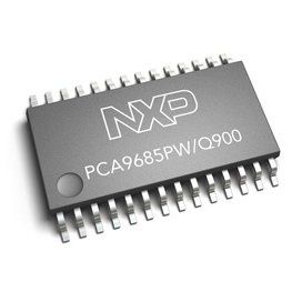
NAVIO: RGB LED and servos with PCA9685 [C++, Python]

This document is not updated, please proceed to docs.emlid.com for latest version!
PCA9685 is a PWM generator chip that can be used to control servos and LEDs. It features:
- 16 channels with separate control
- 12-bit resolution
- Configurable frequency
- I2C operation up to 1MHz
- Output enable pin
PCA9685 is clocked by the 24.576MHz TCXO oscillator and allows to adjust frequency using the PRE_SCALE register. Rising and falling edges for each channel can be set from 0 to 4095 allowing to control duty cycle as well as phase.
Controlling RGB LED
Channels 0, 1, 2 are connected to Navio’s onboard RGB LED. Since that is a LED with a common anode the logic is inverted – lowest value (0) will result in max brightness for the channel and vice versa.
Controlling servos
Channels 3-15 are available on 2.54mm header pins numbered 1-13 accordingly. Servos can be controlled by setting the correct frequency (50hz is a common frequency) and duty cycle corresponding to the length of a pulse (usually between 1 and 2 milliseconds).
To try to control servo connect the servo to the Navio’s output channel number 1 and run the provided example.
[C++]
LED example
Move to the folder with the source code, compile and run the example
cd Navio/C++/Examples/LED
make
sudo ./LED
In this example channels values for RGB LED are slowly decreased and increased creating the mix of different colors.
#include "Navio/PCA9685.h"

int main()
{
    PCA9685 pwm(RASPBERRY_PI_MODEL_B_I2C, PCA9685_DEFAULT_ADDRESS);
    // PCA9685 pwm(RASPBERRY_PI_MODEL_A_I2C, PCA9685_DEFAULT_ADDRESS);

    pwm.initialize();

    uint16_t R = 0, G = 0, B = 4095;

    pwm.setPWM(0, R);
    pwm.setPWM(1, G);
    pwm.setPWM(2, B);

    while (true) {
        for (R = 0; R < 4095; R++)
        pwm.setPWM(0, R);
        for (B = 4095; B > 0; B--)
        pwm.setPWM(2, B);

        for (G = 0; G < 4095; G++)
        pwm.setPWM(1, G);
        for (R = 4095; R > 0; R--)
        pwm.setPWM(0, R);

        for (B = 0; B < 4095; B++)
        pwm.setPWM(2, B);
        for (G = 4095; G > 0; G--)
        pwm.setPWM(1, G);
    }

    return 0;
}
Servo example
Move to the folder with the source code, compile and run the example
cd Navio/Examples/Servo
make
sudo ./Servo
In this example we perform the following:
- Initialize the PCA9685
- Set the frequency
- Set the channel’s value thus controlling the pulse length.
To set the pulse range appropriate for your servo you can change the SERVO_MIN and SERVO_MAX values.
#define NAVIO_RCOUTPUT_1 3
#define SERVO_MIN 1.250 /*mS*/
#define SERVO_MAX 1.750 /*mS*/

#include "Navio/PCA9685.h"

int main()
{
    PCA9685 pwm(RASPBERRY_PI_MODEL_B_I2C, PCA9685_DEFAULT_ADDRESS);
    // PCA9685 pwm(RASPBERRY_PI_MODEL_A_I2C, PCA9685_DEFAULT_ADDRESS);


    pwm.initialize();
    pwm.setFrequency(100);

    while (true) {
        pwm.setPWMmS(NAVIO_RCOUTPUT_1, SERVO_MIN);
        sleep(1);
        pwm.setPWMmS(NAVIO_RCOUTPUT_1, SERVO_MAX);
        sleep(1);
    }

    return 0;
}
[Python]
LED example
Move to the folder with the code and run the example
cd Navio/Python/LED
sudo python LED.py
Servo example
Move to the folder with the code and run the example
cd Navio/Python/Servo
sudo python Servo.py
PCA9685 registers
Here’s a short description of the registers:
0x00 – MODE1 – controls sleep, restart, auto-increment, external clocking, addressing
0x01 – MODE2 – controls inversion, output condition, drive type
Settings for additional addresses
0x02 – SUBADDR1
0x03 – SUBADDR2
0x04 – SUBADDR3
0x05 – ALLCALLADDR
Channel control registers:
0x06 – LED0_ON_L – low byte of 12-bit word for rising edge of channel 0
0x07 – LED0_ON_H – high byte of 12-bit word for rising edge of channel 0
0x08 – LED0_OFF_L – low byte of 12-bit word for falling edge of channel 0
0x09 – LED0_OFF_H – high byte of 12-bit word for falling edge of channel 0
Registers for other channels are similar and their addresses are shifted by 4 per channel, for example, channels for LED1 are:
0x0A – LED1_ON_L
0x0B – LED1_ON_H
0x0C – LED1_OFF_L
0x0D – LED1_OFF_H
To control all channels at once it is possible to use ALL_LED registers:
0xFA – ALL_LED_ON_L
0xFB – ALL_LED_ON_H
0xFC – ALL_LED_OFF_L
0xFD – ALL_LED_OFF_H
To set the frequency use the following register:
0xFE 0 PRE_SCALE – minimal value is 3
How does the PCA9685 C++ driver work?
At first, we call for initialize() method which restarts the device by first setting the SLEEP_BIT to ‘0’ in MODE1 register and then setting the RESTART_BIT to ‘1’ in the same register. Also, it sets the AI_BIT to ‘1’ which allows to perform multi byte I2C operations for faster data transfer.
setFrequency() method is used to control the output frequency. It calculates the prescale value based on the required frequency and writes it to the PRE_SCALE register.
setPWM() method allows to set the duty cycle from 0 to 4095 for the output channel. It can be used to control LED’s brightness. It writes four bytes of data representing the rising edge (LED_ON) and falling edge cycles (LED_OFF) to the following registers: LEDx_ON_L, LEDx_ON_H, LEDx_OFF_L, LEDx_OFF_H where x is the output channel number.
setPWMmS() or setPWMuS() methods allow to set the pulse length of the output channel. It can be used to control servos or other PWM-controlled devices. Internally, they use setPWM() method to set the duty cycle which is calculated based on the required length and the clock frequency.
To get more information about PCA9685 please refer to the PCA9685 data sheet.