Navio: Getting started

This document is not updated, please proceed to docs.emlid.com for latest version!
In this guide we’ll describe how to start working with Navio board including mount, powering up, setting up operating system on Raspberry and much more.
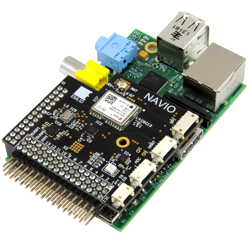
Mounting Navio on Raspberry Pi
Navio was designed to fit on top of Raspberry Pi Model A and Model B, however it also works with Raspberry Pi Model B+ due to the backward compatibility between them. Mounting hole is 2.9mm to accommodate M2.5 screw or bolt.
Powering Navio and Raspberry Pi
From the single power source over USB
This method could be used for working with sensor data only. Raspberry Pi powers the Navio board but no voltage on the servo rail is present. 5VRPI pin on header corresponds to Raspberry Pi 5V network and is directly connected to USB source. Never connect two power sources to this network at the same time, it will damage the power supply.
If you just want to do PPM decoding or power something over the servo rail you can add a jumper between 5VRPI and BEC. This way the whole servo rail is powered from the Pi, please do not connect servos in this configгration, it will cause voltage spikes and Raspberry Pi will reboot. Use power adapters that can handle at least 1A of current.
From separate power sources over 5VRPI and BEC power inputs on servo header
In case you want to control servos, motors or other high power loads it is necessary to use separate power sources for Navio servo rail and Raspberry Pi since the latter is very sensitive to voltage dropouts. Use two BECs or another DC sources that provide 5V and connect them to 5VRPI and BEC inputs on Navio board.
5VRPI input should be strictly 4.75-5.25V.
BEC input is used only for servos and RGB LED and can handle 4.5V-5.5V.
Voltage levels on ports and headers
Servo rail power pins – 5V
Servo rail PWM pins – 5V
PPM input pin – 5V
UART, SPI, I2C port power pins – 5V
UART, SPI, I2C signal pins – 3.3V (CAUTION! connecting 5V logic device to these pins may damage your Raspberry Pi!)
ADC power pin – 3.3V output
ADC signal pins – 0V-3.3V input
Setting up Raspbian
We have an image of Raspbian with all the required configurations available for download. It features real-time kernel with lower latency than default kernel. You can get it here – Real-time Linux. If you want to use default Raspbian then some configuration is necessary – SPI and I2C have to be enabled.
SSH to Raspberry Pi and edit the configuration file:
sudo nano /etc/modprobe.d/raspi-blacklist.conf
This will open a text editor, now change
blacklist spi-bcm2708
blacklist i2c-bcm2708
to
#blacklist spi-bcm2708
#blacklist i2c-bcm2708
Then press CTRL-C and answer Yes to save the file.
To set SPI and I2C modules to load on boot edit /etc/modules:
sudo nano /etc/modules
Add these strings if not present:
spi-bcm2708
i2c-bcm2708
spi-dev
i2c-dev
Save the file and reboot.
After the reboot check that /dev/spidev0.0, /dev/spidev0.1 and /dec/i2c-1 are present in the system.
Detecting I2C devices with i2cdetect tool
Tool called i2cdetect allows you to see devices connected to the I2C bus. It’s avaiable in the package i2c-tools, to install it run:
sudo apt-get install i2c-tools
Run it like this:
sudo i2cdetect -y 1
Where 1 is the number of I2C bus.
The result should look like this:
0  1  2  3  4  5  6  7  8  9  a  b  c  d  e  f
00:          -- -- -- -- -- -- -- -- -- -- -- -- --
10: -- -- -- -- -- -- -- -- -- -- -- -- -- -- -- --
20: -- -- -- -- -- -- -- -- -- -- -- -- -- -- -- --
30: -- -- -- -- -- -- -- -- -- -- -- -- -- -- -- --
40: 40 -- -- -- -- -- -- -- 48 -- -- -- -- -- -- --
50: 50 51 -- -- -- -- -- -- -- -- -- -- -- -- -- --
60: -- -- -- -- -- -- -- -- -- -- -- -- -- -- -- --
70: 70 -- -- -- -- -- -- 77
You should see all devices that responded to their addresses.
Addresses of onboard devices
I2C devices:
- ADS1115 – 0x48
- MS5611 – 0x77
- MB85R – 0x50, 0x51
- PCA9685 – 0x40, 0x70 (allcall address)
SPI devices:
- U-blox NEO – /dev/spidev0.0
- MPU9250 – /dev/spidev0.1
Using UART port
By default UART on Raspberry Pi is used for serial console. To use UART for custom data serial console has to be disabled. It can be done by using the rpi-serial-console tool. To install it run:
git clone https://github.com/lurch/rpi-serial-console
cd rpi-serial-console
make
make install
Then run it with ‘disable’ argument:
rpi-serial-console disable
Now you can use /dev/ttyAMA0 as a UART.