Navio: Decoding PPM to PWM on Raspberry Pi [C++]

This document is not updated, please proceed to docs.emlid.com for latest version!
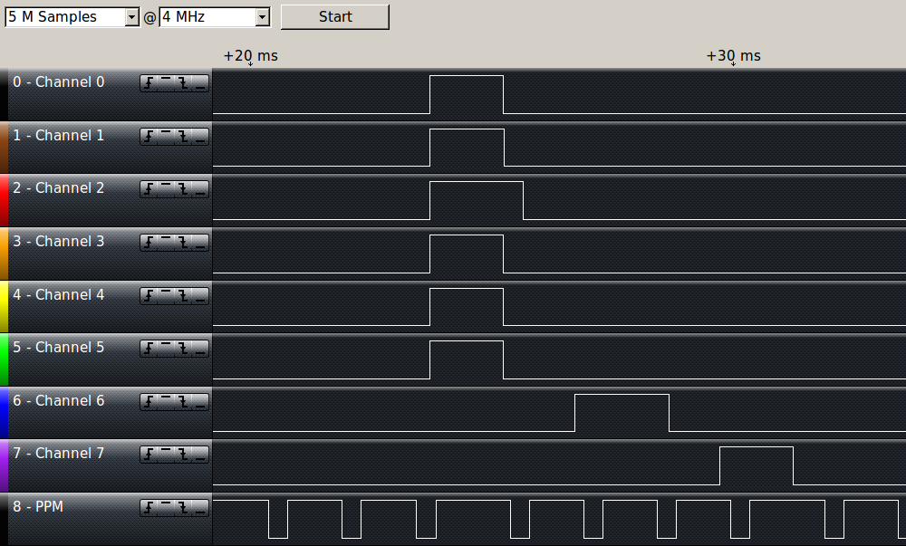
To be used in autopilot applications Navio needs to decode RC input. Measuring each PWM channel requires multiple connectors and plenty of wires. PPM sum signal combines all PWMs from the receiver in one sequence, which could be transferred over single wire.
Most modern receivers output PPM, but if you have an older RC gear with only PWM output an encoder can be used. For the S.Bus receivers we are preparing a separate driver, however a S.Bus to PPM converter exists.
In case you want to run the code on Raspberry Pi without Navio please note, GPIOs on Raspberry Pi are not 5V tolerant. A divider is required to lower the voltage of the signal. Navio has a built-in voltage divider in PPM Input that lowers the voltage level from 5V to 3.3V
We use pigpio library that is capable of sampling GPIO with 1 microsecond resolution over the DMA. The application makes time marks of all edges both rising and falling and measures the delta time between them. If that time is the size of a sync pause, then it is the start of the cycle. After the start of the cycle it measures pulse lengths and stores them.
The acquired PWM values can be used in an application or transferred to the Navio’s onboard PWM generator as it is shown in the video.
Running PPM example
Example code is available in our GitHub repository, if you haven’t previously downloaded it, do:
git clone github.com/emlid/Navio.git
To compile and and run the example navigate to the directory with it, then run make and execute the compiled binary:
cd Navio/C++/Examples/PPM-decoder
make
sudo ./PPM
Now you can connect PPM output from your RC receiver to the PPM Input pin on Navio and connect servos to RC Output channels 1-8 on Navio. Servo rail power (BEC) also must be connected. Channel values sent by remote controller will be decoded and passed to servos as seen in the video.